The Proportional, Integral, Derivative (PID) controller has become ubiquitous in control engineering for its use in closed-loop control of various types of processes. It is not the only means of implementing such control, but it is the most common by a wide margin due to its flexibility and relative ease of implementation.
Nearly every PLC manufacturer includes a built-in instruction for implementing a PID with fairly simple configuration, and so it finds use in all manner of processes. Here, we’ll provide a cursory overview of what a PID does and provide some instruction on how best to implement one to control a process.
Note: This post assumes the reader is familiar with the concept Laplace transformations and how they are used to describe the closed-loop behavior of various systems.
The Basics of PID
The PID at its simplest is a style of control that looks at where the process is relative to its setpoint, how long it has been there, and where it is heading. Each of these three characteristics are weighted according to the proportional, integral, and derivative gains supplied to the controller to determine the control action required to close the distance to setpoint (the error) to zero and keep it there.
How these gains should be determined depends on the type of process being controlled and on the desired “trajectory” the process will take to get back to setpoint. The determination of these gains is what we refer to as PID tuning.
PID Tuning Methods
There are many methods of PID controller tuning, but all of them rely on determining mathematical characteristics describing the nature of the process being controlled and using these to calculate gains that will provide a desired response trajectory. These characteristics are either determined empirically through testing with a running system or (more rarely) calculated from more readily available information such as equipment sizes and other technical data. When it is used, the latter method is often later refined during commissioning using the former method to account for modeling errors.
Some of these methods have names that may be familiar to the reader: Ziegler Nichols, Cohen Coon, lambda tuning, and others. Each of these can be expected to provide good performance in certain circumstances, and each can also be expected to provide suboptimal performance in other circumstances. This largely stems from incongruities between the types of processes the methods are designed for and the type of process actually being controlled. There is only one method of process control that provides consistent results for every process type: closed-loop inversion.
PID Tuning in Practice
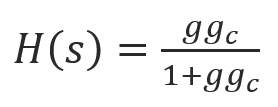
Closed-loop inversion is the calculation of the controller model that must be used in order to “invert” the process model and provide a desired response trajectory. The core of this method is the Laplace transformation of a closed-loop system consisting of a process, g, and it’s controller, gc. The system trajectory, H, will be…
(1) 
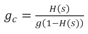
…which can be rearranged to show that the controller model needed to generate a chosen response trajectory for a particular process is given as…
(2) 
We will also note that a PID controller is given by the following form for gc…
(3) 
…where Kc, τi, and τd are the controller gain, reset time, and derivative time for a dependent-form PID. Thus, if the solution of equation (2) can be rearranged in the form of equation (3), the PID gains can be calculated in a straightforward fashion. Take the following example for a simple first-order process and desired response trajectory:
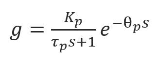
(4) 
…where Kp, τp, and θp are the process gain, response time, and time delay. Say we desire a similar first-order response trajectory of the form…
(5) 
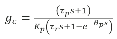
…where τr and θr are the trajectory response time and time delay. If we choose the response trajectory time delay θr = θp, then substituting equations (4) and (5) into equation (2) gives us the controller required to implement this trajectory on this process:
(6) 
This can be implemented directly in an industrial controller but is not in the form given by equation (3) that might let us do this with a simple PID, so we’d need to use custom-built logic to achieve the desired performance. If we want to use a PID to implement this controller, we can do so by first simplifying equation (6) using simple first-order Taylor series approximation for the exponential term, and then rearranging:
(7) 
(8) 
The result given by equation (8) is recognizable as a PI controller by comparing it to equation (3). Furthermore, readers familiar with lambda tuning will notice that the gains provided by equation (7) exactly match those that would be calculated from the lambda tuning method, where λ=τr. Since this result relies upon a low-order approximation of the exponential term, we expect poor performance when process time delay is large, which is a noted weakness of lambda tuning. By using higher-order approximations where needed or by choosing controller algorithms that aren’t simple PIDs, algorithms that provide good performance with long time delays can be readily determined.
Conclusion
Controllers for processes of higher order, unstable processes, lead/lag type process, and more can all be determined through analyses like the one above. Not all response trajectories are possible for all types of processes, but Excel Engineering’s process control team is intimately familiar with employing the techniques required to ensure smooth and predictable operation of any process type.
Attached to this post is a simple spreadsheet that can be used to calculate PID gains for a variety of simple process models with small deadtimes. Simply provide the process model parameters in green and the desired response time constant in yellow. For help with more complicated models, or for help characterizing a system where the process model is poorly understood, contact Excel Engineering for assistance.
[ DOWNLOAD PID TUNING CALCULATOR SPREADSHEET ]
How to use the spreadsheet:
- Input process model parameters in green cells
- Input desired response time constant in yellow cells
More about PID tuning can be found here: You can tune a loop, but you can't tuna fish
About Excel Engineering
Since 1990, Excel Engineering has helped industrial manufacturing, utility, and life sciences clients bolster their workforces and processes in a way that saves on labor costs, improves efficiency, and that ultimately produces a better bottom line. From electrical design and industrial automation to power systems studies and construction management, we have everything you need under one roof, and are just the right size to deliver on it day in and day out.
