Generation Owners of Inverter Based Resources (IBR) on the Bulk Electrical System (BES) are required to have 50% of their assets compliant with NERC PRC-028-1 Disturbance Monitoring and Reporting Requirements for Inverter Based Resources (PRC-028-1) by April 1st 2028 and all assets compliant by January 1st 2030. PRC-028-1 contains eight (8) requirements that Generation Owners must understand so that a proper solution is implemented to ensure compliance. As with any new standard it can be difficult and confusing to understand how to apply it to your existing facility. This post will help clarify the standard and give you a strategy on how to comply with PRC-028-1 on an existing Wind Farm using your existing CTs, PTs and SEL equipment. Let's find out how you can implement PRC-028-1 on your existing Wind Farm.
Why did NERC create PRC-028-1 for IBRs?
Recent disturbance reports (e.g., Blue Cut Fire, Canyon 2 Fire, and Odessa disturbances) have identified a need for disturbance monitoring for Inverter-Based Resources (IBRs) to aid with event analysis, performance monitoring, and disturbance-based IBR generating facility model validation. These disturbance reports recommended installing disturbance monitoring equipment (DME) at wind and solar photovoltaic (PV) resources to ensure adequate data is available for event analysis, performance monitoring, and validating IBR generating facility models. The recommendation included plant-level high resolution oscillography data and plant SCADA data.
Where and what type of data collection is required for PRC-028-1 Compliance?
PRC-028-1 requires that you collect specific data on your system in five main locations.
- Collector Bus Feeder(s)
- High-Side of the Main Power Transformer(s)
- Shunt static and Dynamic Reactive Device(s) – i.e. Capacity Banks
- Inverter-Based Resource unit(s) – i.e. Wind Turbine
- AC-DC and DC-AC converters, if applicable on VSC HVDC system with a dedicated connection to an Inverter-Based Resource
The standard requires three categories of data to be collected, which are listed below. However, not all categories of data apply to all locations on your system. Later on in this post we will examine which categories of data are required for which locations.
- Sequence of Event Recording (SER) – The process of capturing and logging chronological order of events detected by protective relays, such as circuit breaker position (open/close) or system fault codes. This allows for a detailed analysis of system behavior during a fault condition or other event.
- Fault Recording (FR) – A snapshot recording of electrical quantities (current, frequency, voltage) based on a trigger point configured in the system.
- Continuous dynamic disturbance recording (DDR) – A process that continuously records data about a power system’s response and performance during a dynamic event. DDR typically records power swings, frequency variations and oscillation, abnormal voltage and voltage excursions, and system transients.
Implementation of PRC-028-1 on an existing Wind Farm
We will now discuss the application of PRC-028-1 on a simple Wind Farm. Figure 1 shows a simple Wind Farm system with one (1) capacitor bank and one (1) main power transformer. This system has Intelligent Electronic Devices (IED) on the Collector Feeder Breakers, Main Power Transformer and Capacitor Bank. Listed below are the typical Schweitzer Engineering Laboratories (SEL) IEDs that are typically already included on existing Wind Farms in the United States.
- SEL-351S on the Collector Feeder Breakers
- SEL-351S on the high-side of the Main Power Transformer
- SEL-487V on the Capacitor Bank
The good news is that all of these IEDs (typically pre-existing) can be used to comply with PRC-028-1 with some simple re-configuration. In addition to the IEDs, you will also need a SEL Real Time Automation Controller (RTAC) and a SEL Satellite-Synchronize Clock. There are commercially available products that will meet the requirements of the standard:
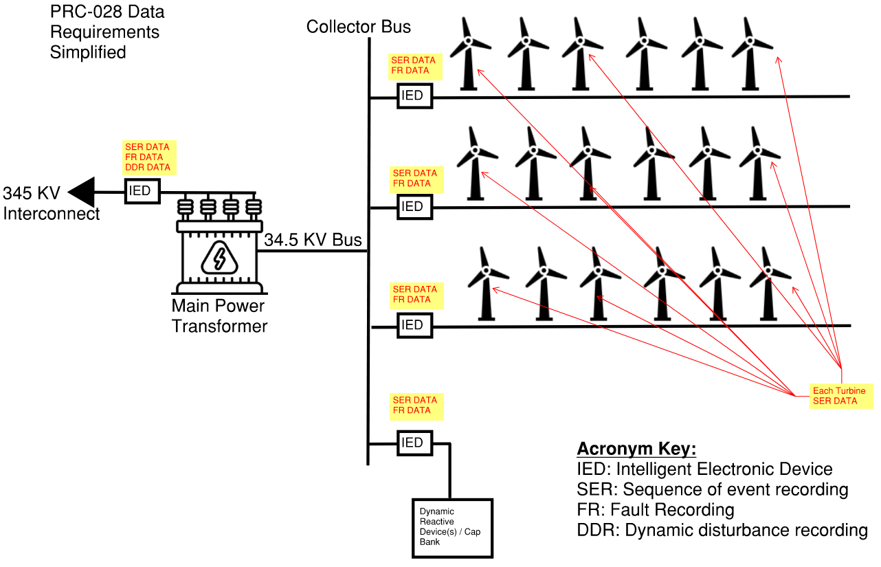
FIGURE 1: PRC-028-1 Data Requirements Simplified
Data collection on the Collector Feeder Breakers
The Collector Feeder Breaker(s) are required to have both SER and FR data types collected. The Collector Feeder Breakers are specifically mentioned in 3 of the 8 PRC-028-1 requirements.
|
PRC-028-1 Requirement |
Category of Data |
Requirement Summary |
Note |
|
R1 |
SER Data |
Circuit Breaker position (open/close) |
|
|
R2 |
FR Data |
|
|
|
R3 |
FR Data |
At a minimum recording rate of 64 samples per cycle you must have trigger settings for the following.
|
Data may be captured in a single record or multiple records that include a pre-trigger record length of two cycles and a total record length of at least 2.0 seconds for the same trigger point. NOTE: The SEL-351S is only able to capture 1 second of data for a trigger point. However, the standard allows for multiple records to be captured on the same trigger point, which the SEL-351S can accommodate.
|
TABLE 1: Requirements for Collector Feeder Breakers
Data collection on the IBR Units
The Wind Turbine(s) are required to have SER data. Wind Turbine manufacturers such as Vestas and GE have multiple communication protocols that they support. However, the industry standard is IEC 61400-25. IEC 61400-25 references a subset of definitions from IEC 61850 and defines domain-specific and common logical nodes (LNs), data objects, and data classes for wind power plants. SEL RTACs support communication to IEC 61850 devices, see details below.
|
PRC-028-1 Requirement |
Category of Data |
Requirement Summary |
Note |
|
R1 |
SER Data |
|
Data collection must be triggered by ride-through operation or tripping an IBR Unit. |
TABLE 2: Requirements for IBRs
Data collection on the Capacitor Bank
Similar to the Collector Feeder Breakers, the Capacitor Banks are required to have both SER and FR data types collected. The Capacitor Banks are also mentioned in 3 of the 8 PRC-028-1 requirements.
|
PRC-028-1 Requirement |
Category of Data |
Requirement Summary |
Note |
|
R1 |
SER Data |
Circuit Breaker position (open/close) |
|
|
R2 |
FR Data |
|
|
|
R3 |
FR Data |
At a minimum recording rate of 64 samples per cycle you must have triggers settings for the following.
|
Data may be captured in a single record or multiple records that include a pre-trigger record length of two cycles and a total record length of at least 2.0 seconds for the same trigger point. NOTE: The SEL-351S is only able to capture 1 second of data for a trigger point. However, the standard allows for multiple records to be captured on the same trigger point, which the SEL-351S can accommodate.
|
TABLE 3: Requirements for the Capacitor Bank
Data collection on the Main Power Transformer
The Main Power Transformer is required to have SER, FR and DDR data types collected. Data needs to only be collected on the high-side of the Main Power Transformer which is specifically mentioned in 5 of the 8 PRC-028-1 requirements.
|
PRC-028-1 Requirement |
Category of Data |
Requirement Summary |
Note |
|
R1 |
SER Data |
Circuit Breaker position (open/close) |
|
|
R2 |
FR Data |
|
|
|
R3 |
FR Data |
At a minimum recording rate of 64 samples per cycle you must have triggers settings for the following.
|
Data may be captured in a single record or multiple records that include a pre-trigger record length of two cycles and a total record length of at least 2.0 seconds for the same trigger point. NOTE: The SEL-351S is only able to capture 1 second of data for a trigger point. However, the standard allows for multiple records to be captured on the same trigger point, which the SEL-351S can accommodate.
|
|
R4 |
DDR |
|
|
|
R5 |
DDR |
All the electrical quantities that are collected in R4 above must be collected with:
|
|
TABLE 4: Requirements for the Main Power Transformer
General Requirements
Requirements R6 through R8 discuss the need for Time Synchronization on all devices, how long and what format the data should be archived, and corrective action plan upon discovery of a data recording failure.
|
PRC-028-1 Requirement |
Requirement Summary |
Note |
|
R6 |
All SER (Sequence of Events Recorder), FR (Fault Recorder), and DDR (Dynamic Disturbance Recorder) data must be synchronized to Coordinated Universal Time (UTC), with or without a local time offset. |
SEL-2407 (Satellite-Synchronized Clock) or SEL-2488 (Satellite-Synchronized Network Clock) can be use to satisfy this requirement. |
|
R7 |
Data must be retrievable for a period of 20 calendar days, inclusive of the day the data was recorded. It must be provided to the requesting authority with 15 days of the request. |
Data storage requirements and naming conventions can be natively handled by the existing SEL IEDs and RTAC equipment. |
|
R8 |
If data recording failure is discovered on the system, you have 90 calendar days to correct the issue and you must submit a Corrective Action Plan to the Regional Entity with your planned fix for the issues. |
|
TABLE 5: General Requirements
Pulling it all together with an RTAC
A SEL Real Time Automation Controller (RTAC) is similar to a Programmable Logic Controller (PLC) and supports IEC 61850 (defines how IEDs communicate with each other in electrical substations) and IEC 61131-3 (Standard for PLC Programming Languages). SEL has several models of their RTAC product but to comply with the requirements of PRC-028-1 you will need either the SEL-3555 or the SEL-3350 with the “Dynamic Disturbance Recorder” and “Continuous Recording” options enabled in firmware. If you have an older RTAC model like the SEL-3505, this does not have the ability to perform the necessary Fault Recording (FR) or Dynamic Disturbance Recording (DDR) required by PRC-028-1. However, you can purchase a new RTAC and convert the logic and configuration from your older model to a compatible RTAC model as part of your compliance project.
In addition to any logic or configuration you have in your RTAC you must add and configure the Digital Fault Recorder and Dynamic Disturbance Recorder extensions into your projects. Then, you must add and configure the appropriate IEDs and IBR Units to collect the data defined in the requirements above.
Once the RTAC is configured, you must test your data collection in a test setup or lab environment to ensure you have configured the proper triggers and are collecting the proper data for the appropriate amount of time. This will also allow you to determine where you are going to store the event data (on the RTAC memory or on a server) and how to interface with the data. After your Factory Acceptance Testing, you can deploy your project to the field.
Conclusion
Most modern BES Wind Farms and Solar Farms already have most of the proper IEDs installed in the appropriate locations making compliance with NERC PRC-028-1 simply a matter of reengineering existing equipment rather than completely overhauling the existing facility which avoids large capital investment and equipment downtime.
As mentioned above, the PRC-028-1 offers a clear strategy (i.e. – eight requirements) for achieving compliance. Still, Generation Owners of Inverter-Based Resources on the Bulk Electrical System must act now to ensure that by April 1st, 2028, 50% of assets are compliant and by January 1st, 2030, all assets are compliant. This standard can be challenging to apply to your existing facilities, but this document provides a clear strategy for compliance using your existing CTs, PTs, and SEL equipment.
If your team is already resource-constrained or you are unsure where to start, Excel Engineering can help with all aspects of this process, from consulting on a path to compliance to a turnkey project.